Temperature Sensor Circuit
Before building the display, you will connect the temperature sensor to the Arduino and display the temperature on the Serial Monitor in the Arduino IDE.
Disconnect the Arduino board from the computer and construct the circuit pictured on this page.
Important Notes
- Place the temperature sensor exactly where indicated so that you have enough space to build the display on the rest of the breadboard later.
- Use the small pieces of wire to connect the temperature sensor to power and ground to prevent your circuit from getting too messy.
- Use the same colour of wires as those shown in the diagram to make it easier to fix problems with your circuit.
- The 5V and ground connections to the bottom of the breadboard will be used later when building the display.
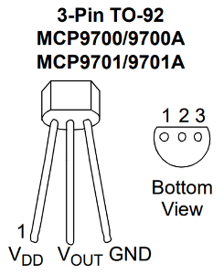
In the circuit pictured below, the flat side of the temperature sensor is facing the empty half of the breadboard. It is important to orient the the temperature sensor this way so that you do not connect the power backwards. With the flat side of the sensor facing you, the pins have the following functions from left to right: power, sensor output, ground. See the pin diagram below from the sensor's datasheet below.

The blue component (the one you have is yellow) behind the temperature sensor is a 0.1µF (0.1 microfarad) capacitor. It should be placed as close as possible to the temperature sensor, and is connected across the power and ground pins of the sensor.
What's a capacitor?
A capacitor is a circuit component which stores electrical energy in an electric field. A simple capacitor could be built by placing two metal plates parallel to each other, a small distance apart. In between the plates, there is an insulator (known as a dielectric).
It may seem that you are creating a short circuit by putting a capacitor across the power and ground pins, however the plates in a capacitor are separated by an insulator. This means that the capacitor will not conduct the direct current (DC) that is supplied to the sensor by the Arduino. In this circuit, the capacitor is used to reduce noise (fluctuations in the power supply voltage) in the power supplied to the sensor.
The capacitor you are using in this circuit can be connected either way. It does not matter which pin is connected to 5 volts and which is connected to ground. Note that other types of capacitors are polarized, meaning there is a specific way they must be connected.

Check your Circuit
Before continuing, check your circuit to confirm it is wired correctly. Ask a mentor to double check the circuit after you have checked it.